
Numerical Study of Bearing Strength of Infilled Concrete in Large Diameter CFST Column Reinforced by Shear Stoppers

Faculty of Civil Engineering, University of Science and Technology-The University of Danang, 54 Nguyen Luong Bang, Danang 550000, Vietnam
*
Author to whom correspondence should be addressed.
Designs 2024, 8(1), 9; https://doi.org/10.3390/designs8010009 (registering DOI)
Submission received: 4 December 2023
/
Revised: 3 January 2024
/
Accepted: 9 January 2024
/
Published: 16 January 2024
(This article belongs to the Topic Resilient Civil Infrastructure)
Abstract
:Ensuring an adequate bond between the steel tube and infilled concrete interface plays an essential role in achieving composite action for concrete-filled steel tubular (CFST) columns. Thus, this study proposes a new type of large diameter CFST column where the steel tube is reinforced by shear stoppers. The bearing strength of the infilled concrete is the decisive factor in evaluating the overall working efficiency between infilled concrete and steel tube. In this paper, we use nonlinear finite element analysis (NFEA) to investigate the bearing strength of the infilled concrete concerning the ratio of the steel tube’s diameter to its thickness , the number of shear stoppers , the height of the shear stopper , and the concrete compressive strength (CCS) . Our results show that the influencing factors on the bearing strength of the infilled concrete were arranged in descending order as follows: the number of shear stoppers, the height of shear stopper, the CCS, and the ratio. We also analyze and highlight some significant parameters related to the bearing strength of infilled concrete.
1. Introduction
In recent years, the demand for concrete-filled steel tube (CFST) columns has been increasing. CFST columns are becoming a popular replacement for traditional reinforced concrete columns and are widely used in residential and high-rise buildings as well as in bridge structures [1,2,3,4]. CFST columns offer several advantages: high stiffness [5], high fire resistance [6,7,8], and ease of construction without the need for formwork systems [6]. CFST column/kingpost/pile is particularly effective in the construction of basements using the top-down method or in the construction of CFST arch bridges. Moreover, the construction of CFST columns can reduce construction costs and shorten construction time [5,9]. However, due to the unique properties of CFST columns, which are composed of two materials with different stress–strain behaviors, their structural resistance mostly depends on the combination of these materials. Therefore, it is difficult to understand the working mechanism at the interface between them [10]. This is also the reason why, to date, the interaction between the two materials has not been fully evaluated [10]. For example, it is challenging to determine the combined properties of CFST’s cross-section, such as the equivalent modulus of elasticity or moment of inertia. Additionally, the failure mechanism is influenced by several factors, including the diameter, steel tube thickness, length, cross-section shape, and concrete and steel strength. This poses a significant barrier to the widespread use of CFSTs in the construction field. In practice, CFST behavior depends on numerous factors, such as concrete confinement, residual stress, shrinkage, creep, type of loading, bonding, etc. These parameters interact with each other during the column’s service life. Many studies have been conducted on these issues so far, which can be summarized as follows:
The bearing strength of Infilled concrete was initially studied through research on the bonding strength between infilled concrete and steel tube. Before 1980, it was assumed that the interaction between concrete and steel tube resulted in a perfect bond when the column was progressively loaded until failure [11,12]. During that time, Furlong [13], Virdi and Dowling [14], and Shakir-Khalil et al. [15] also mentioned the strain compatibility between concrete and steel tubes, but the bond between concrete and steel was not studied as separate entities. It is important to note that most studies evaluating the bond strength of CFST columns use the push-out test [16,17,18], and the bond strength can be classified into two types as follows:
The first type is characterized by a flat inner surface of the steel tube, without any bonded stiffeners, shear studs, or stoppers to reinforce it. From 1975 to 1980, the study conducted by Virdi and Dowling involved push-out tests on concrete-filled circular tubes [19,20], where the inner surface of the steel tube was left in its natural state. This can be considered the first study to examine the bond between concrete and steel tube as separate entities. The tests investigated various parameters, such as the surface roughness of steel, the concrete compressive strength, the length-to-diameter ratio for the interface, the ratio of the steel tube’s diameter to its thickness, etc. Research results indicate that the biggest impact on bonding strength was due to imperfections during the manufacture of the tubes. Moreover, these results were utilized by the Joint ECCS–CEB–IABSE–FIP committee in the European code for composite construction. Hunaiti [16] conducted comprehensive research on bonding strength, examining 135 battened specimens and accounting for various influencing factors, such as specimen age and size, curing, temperature, concrete shrinkage, and confinement. The research revealed that columns with battened composite sections had lower bond strength than CFST columns tested elsewhere. Additionally, it was found that the age of the concrete significantly reduced bonding strength. Other factors that contribute to the decrease in bonding strength include concrete shrinkage, confinement, and specimen size. To fully understand the physical nature of the interaction mechanism between concrete and steel tube, Johansson and Gylltoft [21] used finite element analysis (FEA). The results from 13 experimental samples and FEA confirmed that the loading method had the greatest impact on the CFST column’s behavior. Specifically, when loading the concrete and steel tube simultaneously, the bonding strength had no effect on the CFST column’s behavior. However, when only the concrete core was loaded, the bonding strength substantially affected the behavior of the CFST column through the confinement effect. Xiushu et al. conducted another study [18] that assessed the impact of concrete compressive strength, contact surface length, cross-sectional area, and different contact surface conditions on bond strength. The study demonstrated that lubricating the contact surface between the steel tube and the concrete significantly decreased the bond strength. The remaining factors investigated revealed that the concrete compressive strength and the cross-sectional area had a clear effect on bond strength when the specimens were not lubricated. With experimental data, the research team proposed an empirical equation to predict bond strength. For the first type of bond between concrete and steel tube, a new method was proposed by Chang et al. [17] to improve bond strength. Specifically, Chang and colleagues pre-stressed the infilled concrete to control its shrinkage/expansion characteristics. The study results showed that pre-stressed concrete core significantly improved bond strength compared to CFST columns. Additionally, an empirical equation for predicting bond strength was developed based on 17 pre-stressed circular CFST columns using expansive cement and 3 conventional circular CFST columns. In a different study, Guana and colleagues [22] aimed to enhance the bond strength between concrete and steel tube. They proposed using small aggregates, specifically manufactured sand, to produce the infilled concrete. The study revealed that concrete-filled steel tube columns using manufactured sand (MS-CFT) could increase the bond strength. Additionally, the bond strength of MS-CFT was higher than that of conventional CFST columns.
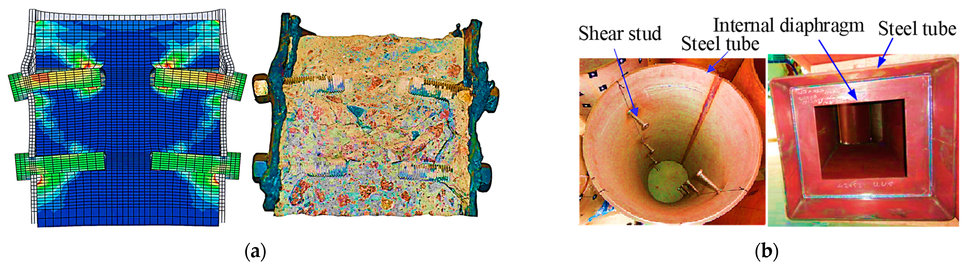
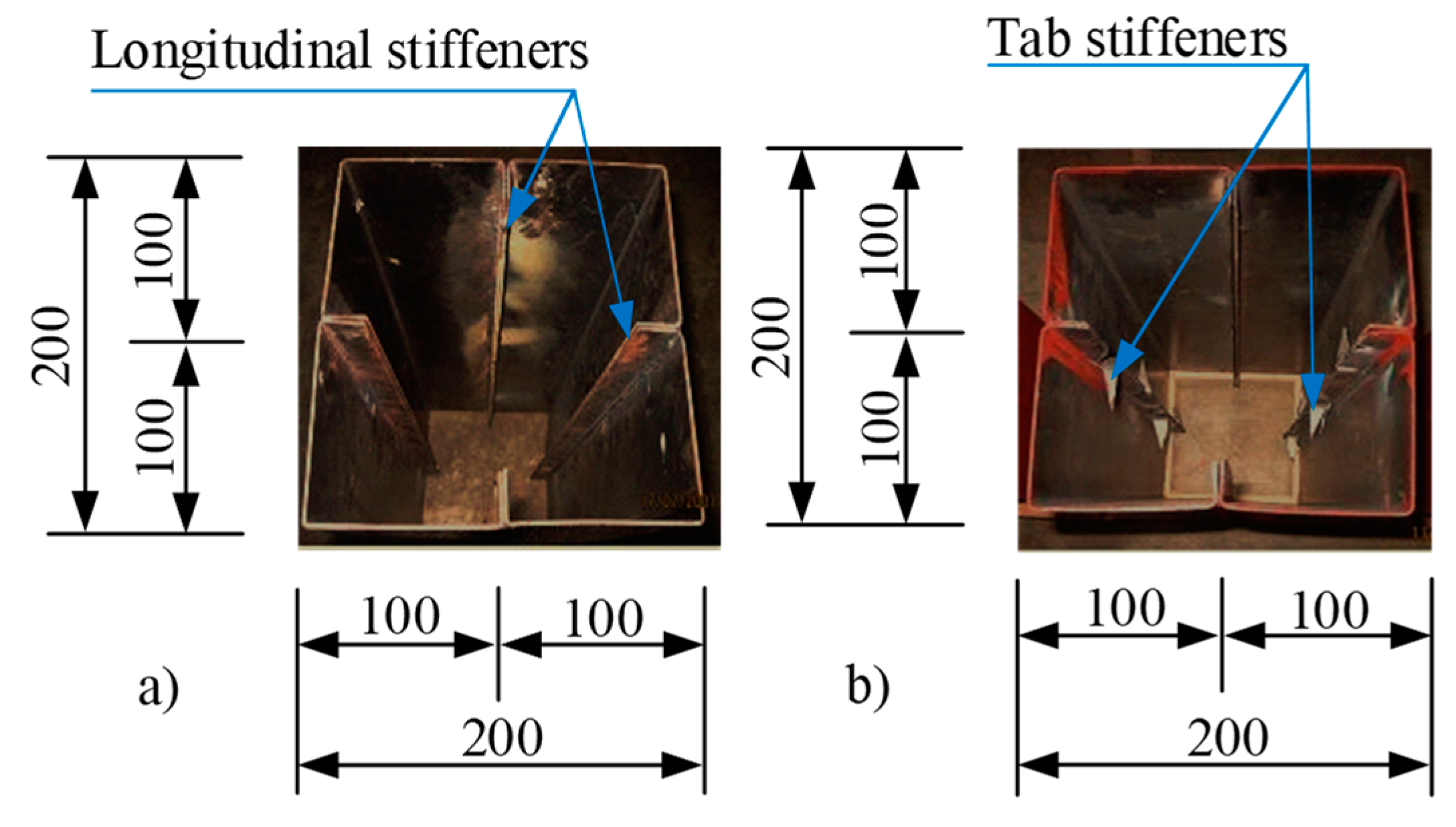
In the second type of bond between concrete and steel tube, the inner surface of the steel tube is reinforced by either a stiffener or a shear stud/stopper. Starossek and Falah [23,24] used shear connectors penetrating the steel tube wall (see Figure 1a) to improve bond strength between concrete and steel tube. During the study, the research team examined 71 specimens, where the shear connectors were reinforced only at the column top where the load was applied. The purpose of the study was to compare the force transfer between the natural bond and the shear connector bond. Additionally, the team performed an NFEA to conduct in-depth analysis. The study results showed that bond strength ranged from 0.8 to 1.0 N/mm2, which was much higher than the value of 0.4 N/mm2 specified in EC4. As the load increased, the shear connectors were subjected to bending or torsion, causing significant deformation, local instability, or plastic flow of the steel tube at the shear connector location. Meanwhile, Petrus et al. [25] implemented a novel approach to enhancing the bond strength of CFST columns, which involved the use of internal stiffeners (as shown in Figure 2) in reinforced steel tubes. The researchers conducted push-out tests on 21 square specimens measuring 200 mm × 200 mm, which were fabricated from mild steel sheeting with a thickness of 2 mm. The results showed that the bond strength at the interface between concrete and steel increased by approximately 40% with the increase in concrete compressive strength or the decrease in tab spacing. Another method to improve the bond strength between infilled concrete and a steel tube is by using shear studs [26,27]. Song et al. [26] conducted a detailed and extensive study on a full-scale model of CFST columns, consisting of eight circular CFST columns with a diameter of 400 mm and five square CFST columns with a width of 600 mm. The study examined the bond strength of experimental specimens under various key experimental parameters, including the type of steel (carbon steel and stainless steel), the type of concrete (normal and lightweight), and the concrete’s age (28 days and approximately 3 years). The contact surface between the concrete and steel tube was tested with three different types: the natural surface of the steel tube, the inner surface of the steel tube reinforced with two rows of shear studs symmetrically arranged through the center of the tube (see Figure 1b), and the surface of the steel tube reinforced by internal diaphragms (see Figure 1b). The research found that CFST column specimens with stainless steel tubes had lower bond strength than those with carbon steel tubes. Additionally, as the concrete age increased, the bond strength decreased considerably. An essential finding was that CFST columns with steel tubes reinforced by internal diaphragms had the highest bond strength, surpassing the case of welding shear studs on the tube’s inner surface. In the method of using expansive concrete, similar to the study by Chang et al. [17], the research results showed that this method was less reliable when applied in practice. Li et al. [28] conducted an experimental study on the bearing strength of a new type of square CFST column reinforced with internal transverse stiffened bars under axial compression. The study demonstrated that the bearing capacity of this column type increased by approximately 4.5% to 15% compared to conventional CFST columns without internal transversely stiffened bars. Additionally, the confinement performance of the infilled concrete in this column type was also improved.
Based on prior research, the bond strength of CFST columns plays a critical role in their performance. The roughness of the concrete–steel interface has been identified as a significant factor affecting bond strength, which deteriorates as concrete ages. The use of expansive or manufactured sand concrete is not an effective means of improving bond strength, nor can it guarantee reliability in construction projects. Additionally, CFST square columns exhibit lower bond strength than their circular counterparts, and increasing the diameter of the infilled concrete and the ratio of diameter to wall thickness of the steel tube results in decreased bond strength [10]. The implementation of an internal diaphragm to fortify the interior of a steel tube has been confirmed to enhance bond strength. However, welding these diaphragms to the inner part of the steel tube presents significant challenges in terms of time, labor, and expense. Furthermore, the placement of internal diaphragms within steel tubes makes it exceedingly difficult to completely fill the under-corner area where the diaphragm meets the steel tube wall during the concrete-pouring process. Recent studies have demonstrated the effectiveness of creating transverse corrugations in columns and shear walls to improve their shear resistance, ductility, and energy-dissipating capacity [29,30]. Moreover, the use of NFEA provides a reliable tool for predicting and evaluating the behavior and performance of structures using materials that work in a linear or nonlinear elastic regime [29,30,31]. This enables a comprehensive analysis of a structure’s physical nature, behavior, and working mechanism, providing extensive information that experimental methods cannot deliver. In this study, a new type of large-diameter CFST column is proposed, wherein the inner surface of the steel tube is reinforced with shear stoppers. The study uses numerical analysis with NFEA to predict and estimate results and to extensively assesses various model parameters to analyze the degree of influence of different factors on bond strength. Analysis of variance (ANOVA) is used to evaluate the interaction between these parameters on CFST column behavior, providing a novel way of analyzing their behavior in depth.
2. Finite Element Analysis for Bearing Strength of Infilled Concrete
2.1. Algorithm
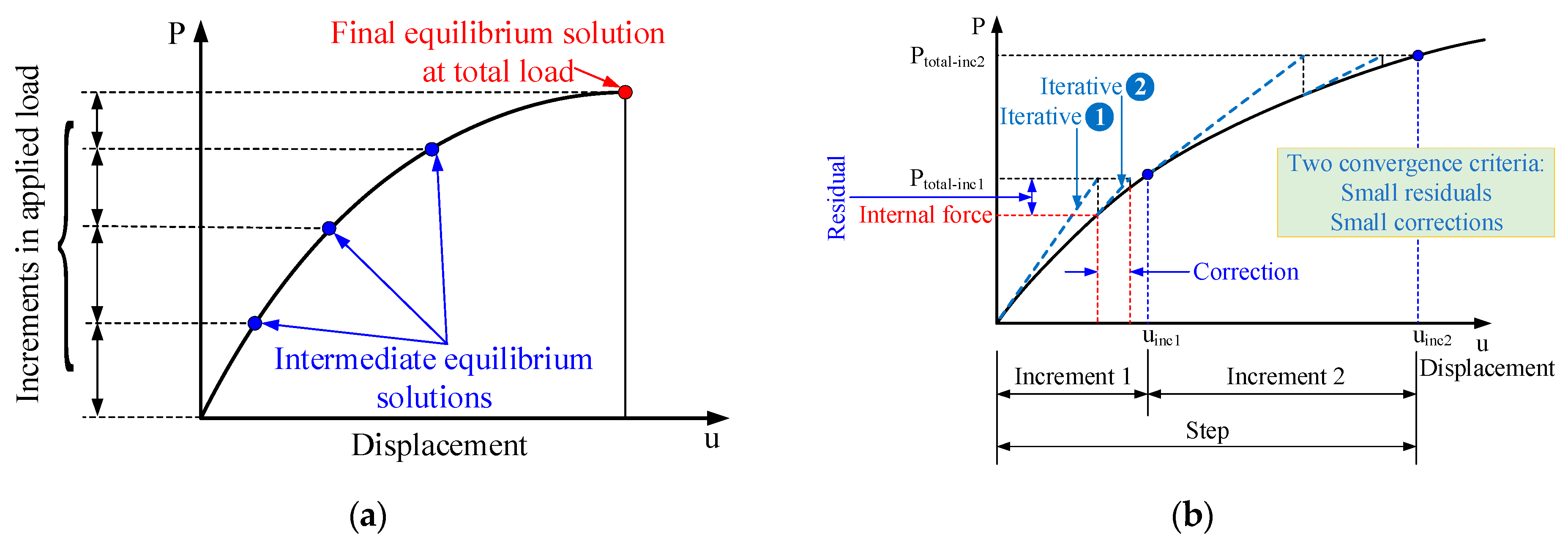
FEA aims to determine the displacement field of structures, ensuring that a continuous solution across element boundaries meets requirements for both equilibrium and the prescribed boundary conditions. The principle of static equilibrium asserts that internal forces acting on the nodes result from element stresses, and the external force acting at every node of the entire structure must be balanced. Mathematically, this principle can be represented by an equation as follows:
Equation (1) represents a nonlinear problem, which cannot provide a direct solution for the displacement field . To solve this problem, this study utilizes Abaqus software 2022. In practice, Abaqus employs an incremental iterative technique based on the Newton–Raphson algorithm (depicted in Figure 3) [32]. It assumes that the known solution at the first loading level is established. After each iteration , an approximate solution is obtained, and is the difference between the approximate and exact solutions. Therefore, the exact solution is required to satisfy Equation (1). Consequently, the equation leads to:
Expanding the left-hand side of Equation (2) with the Taylor series using an approximate solution in the vicinity of , we obtain:
The Newton–Raphson algorithm utilizes the linear diagram in Figure 3. This process enables the derivation of a linear equation system from Equation (3) when higher-order terms (HOTs) are omitted. Therefore, we can obtain a linear equation system as follows:
where represents the tangential stiffness matrix. Therefore, the next approximation of the solution is:
It should be noted that the difference between the total applied force and the internal force after each incremental step is referred to as the residual force. The residual force is represented by , and its computational expression is provided in Equation (6).
When is significantly small in all degrees of freedom of the model, satisfying the convergence criteria, the entire mechanical system is in equilibrium. The default tolerance for is set to less than 0.5% of the time-averaged force in the system, which is automatically calculated. In case the iteration fails to converge, the algorithm executes another iteration to attempt to identify a convergent solution. This process is repeated until the residual force meets the convergence criteria. Each iteration requires:
- Updating the tangential stiffness matrix ;
- Seeking the solution of the linear equation system for , and the estimated solution is provided as ;
- Computing the internal force vector based on , and the equilibrium convergence must be checked after each increment with two conditions: (i) must be within tolerances and (ii) increment .
2.2. Tangential Stiffness Matrix
In FEA, the stress element is computed using the nodal displacement vector of the element, which can be expressed as:
here,
where is the shape function, which is a function of the iso-parameters . The surfaces of the element are located at coordinates , , and . By using FEA, the stiffness matrix is calculated as follows:
The global stiffness matrix is established through the element connection matrix over the number of elements :
2.3. Load Vector
In FEA, the element load vector is computed by taking the sum of the external loads (body loads () and surface loads ()) and internal loads due to initial strain ()/stress (). This leads to
Similar to the stiffness matrix, the global load vector is represented by Equation (12).
2.4. Material Model
2.4.1. Concrete
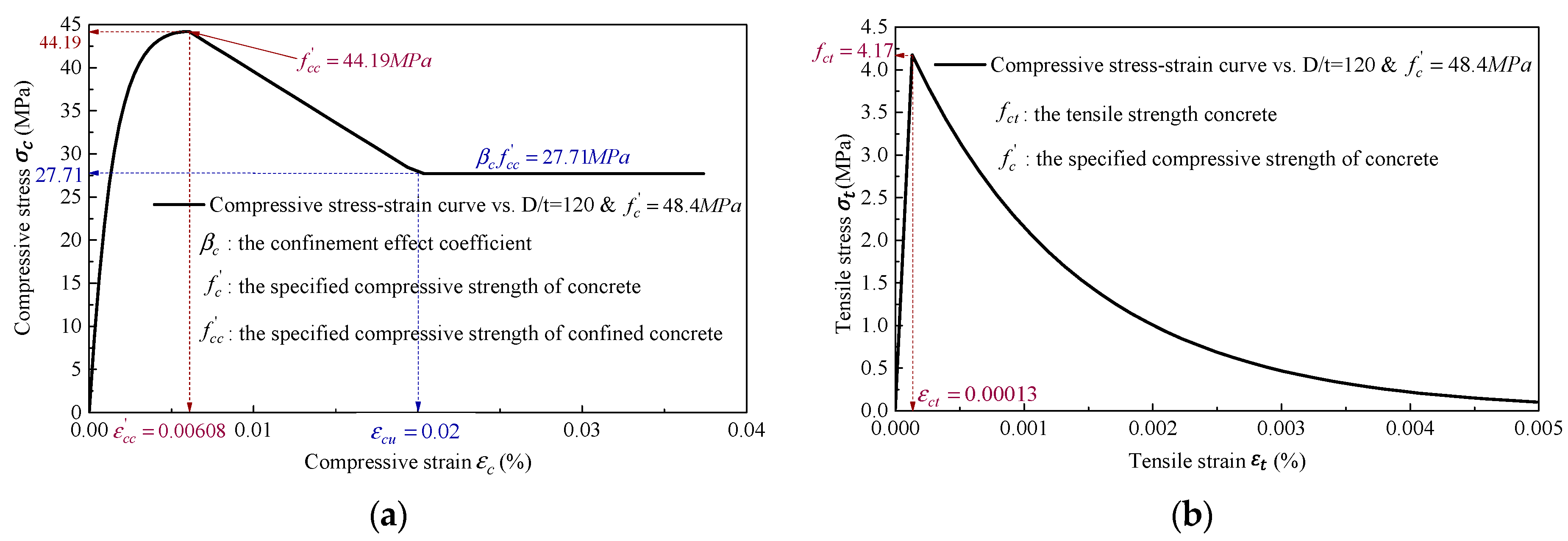
Abaqus utilizes the concrete damaged plasticity (CDP) material model to describe the behavior of reinforced concrete materials. The CDP model is derived from the standard model of CEB-FIP 2010 [33] and the study conducted by Krätzig [34]. It is important to note that the CDP model used in Abaqus does not account for the confinement effect of concrete. However, in this study, concrete was filled into a steel tube and subjected to axial compression, consequently being affected by the confinement effect due to resistance to transverse deformation caused by the steel tube wall. To account for the confinement effect, the CDP model of concrete proposed by Mander et al. [35] and then developed for numerical analysis application by Liang [36,37] was used in this study. The main parameters affecting the confinement effect are the ) ratio between diameter and thickness of the steel tube, the characteristic compressive strength () of the concrete, and the yield strength () of the steel tube. The typical compressive stress–strain and tensile stress–strain curves are shown in Figure 4.
2.4.2. Steel
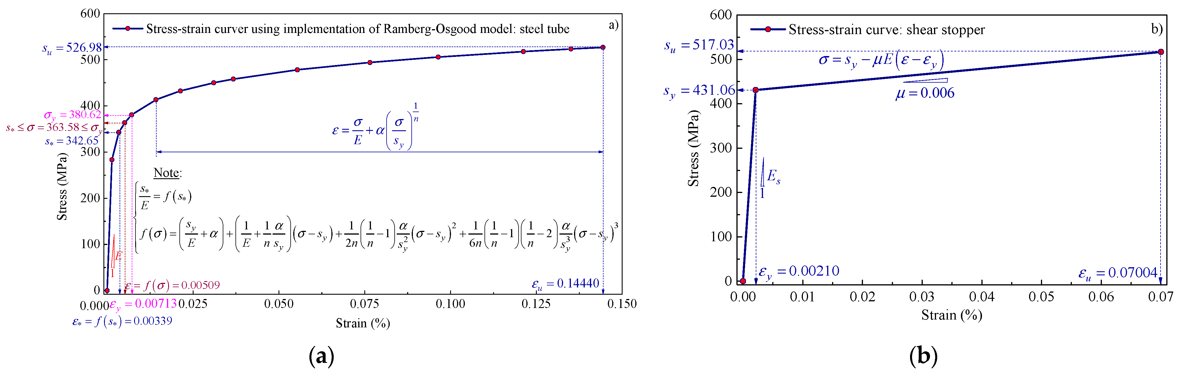
The material models for the steel tube and shear stopper are based on an elasto-plastic model with von Mises yield criteria. Since the shear stopper is of high strength and has small strain characteristics, the Ramberg–Osgood model [38] (as shown in Figure 5a) and an ideal bilinear model [4,39] (as shown in Figure 5b) were implemented to describe the material model for the steel tubes and shear stoppers, respectively. The material behavior curves for the steel tube and shear stopper are depicted in Figure 5.
2.5. Contact Formulation
When a CFST column is subjected to axial force, there is relative sliding between the infilled concrete and the steel tube wall at their interface. Therefore, it is necessary to accurately describe the contact conditions at this interface. In Abaqus, the contact kinematics can be customized for this purpose. In this modeling, surface-to-surface contact is used between the infilled concrete and the steel tube. The motions of secondary surface nodes are attached to the infilled concrete and are used to track the positions of the surrounding main element surfaces, which are attached to the steel tube. Both secondary and main surfaces are associated with deformable bodies, and they constitute a “contact pair” that behaves as a flexible–flexible contact.
There are two approaches to the contact pair formulation. The first approach maintains contact conditions exactly using the Lagrangian multiplier method, which is also known as a “trial and error” algorithm. This method was endorsed in studies by Francawlla and Zienkiewicz [40] and Chan and Tuba [41] and often exerts the Newton–Raphson algorithm introduced by Hughes et al. [42]. However, this approach has a limitation due to the increased number of unknowns from the Lagrangian multiplier, representing contact forces, and the presence of zero diagonal terms in the tangent stiffness matrix associated with the Lagrange multipliers may lead to difficulties in direct solution processes. The second approach maintains contact constraints approximately using the penalty method. Kikuchi and Oden [43] introduced a rigorous mathematical treatment of the penalty method for contact problems. The penalty formulation maintains a simple contact constraint and results in positive definite tangent matrices with positive diagonal terms. However, the penalty procedure often leads to poor conditioning of the tangent stiffness matrix due to the unbounded growth of the condition number as the penalty parameter increases. The choice of an appropriate value for the penalty parameter represents a compromise between significant loss of accuracy due to poor conditioning of the tangent matrix and unacceptable violation of the contact condition. This study used the penalty method, with “hard contact” for normal behavior and tangential behavior set to [44].
2.6. Geometrical and Mechanical Properties of Simulation Models
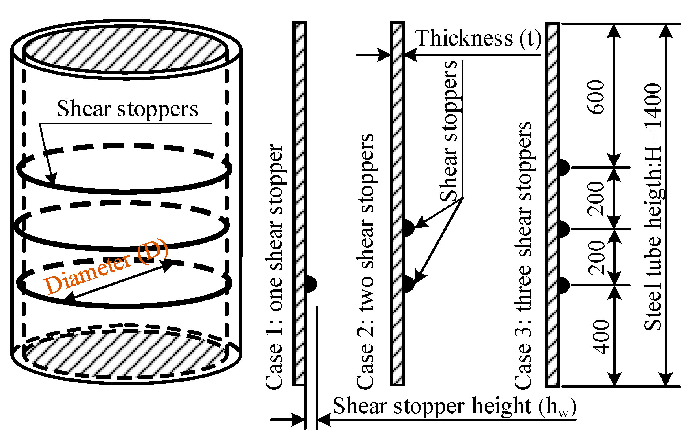
A parametric approach was used for the investigation of bearing strength in CFST columns by changing the geometric and mechanical parameters of the model. The geometry of the simulation model is described in Figure 6. The simulations were conducted on 11 models, corresponding to 11 experimental models currently being implemented. The parameters and mechanical properties of the simulation models are provided in Table 1.
2.7. Mesh Generation and Working Principal Diagram
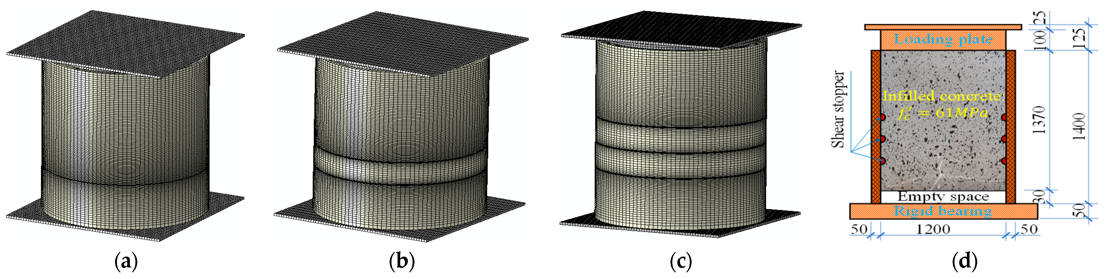
This study employed a parametric approach to analyzing the bearing strength of the infilled concrete in the CFST columns. Theoretical analysis, as described in Section 2.1,Section 2.2,Section 2.3,Section 2.4,Section 2.5,Section 2.6 and Section 2.7, was used to create 11 different models by altering the geometrical and mechanical properties of the concrete and steel tube, as shown in Section 2.6 and Table 1. After determining the geometry and materials, the infilled concrete was discretized using the 3D-stress C3D8R element, an eight-node brick element that uses Gaussian integral reduction technology, with one integral point activated in this study. Since the steel tubes had a relatively large thickness, as indicated in Table 1, and were equipped with shear stoppers, their mechanical behavior was better represented by a continuous eight-node brick element (C3D8R) compared to shell elements. Furthermore, the use of C3D8R elements ensured accuracy in modeling the mechanical behaviors of the tube wall, such as stress–strain relations at tensile and compression layers, with high precision.
Moreover, the C3D8R element utilizes a reduced integration scheme, thereby eliminating shear-locking phenomena. This element facilitates an accurate description of stress–strain relationships at the integration points, although it only uses one quadrature point at the center of the element. To ensure precision in modeling the stress concentration at the corner and boundary positions of structures, a meshing element with a small size is necessary. The one-point integration used may result in hourglass modes or spurious zero energy modes that can corrupt a particular solution. However, hourglass modes are rare in well-meshed structures and cannot spread throughout a conventional mesh. When hourglassing modes occur, the solution fails to converge. Nonetheless, generating a good mesh can help overcome this issue. Even when subjected to a complex stress state, an element using one integration point is less prone to shear-locking phenomena, making the C3D8R element the ideal choice for current simulations.
To apply load to the infilled concrete, a loading plate was used, and to secure the column bottom, a base plate was also used (see the working principal diagram in Figure 7d). The mesh for the loading and base plates was generated using the rigid element, a set of nodes where the motion is governed by a unique node known as the reference node for a rigid body. The shape of a rigid body can be defined as an analytical surface obtained by either rotating or sliding a 2D geometrical profile or its discretization obtained by meshing its nodes and elements. The shape of the rigid body remains constant throughout the simulation and may undergo a finite motion. The mass and inertia of a discrete rigid body can be computed based on the distribution of rigid elements or can be assigned directly.
Rigid body motion can be defined by imposing boundary conditions on its reference node. The load on a rigid body is generated by a concentrated load acting on the nodes, a distributed load acting on the element, or the loads applied to the reference node of the rigid body. Rigid bodies interact significantly with the rest of the model through nodes connected to the deformation elements and through contact with the deformation elements. The fine meshes of three typical models are presented in Figure 7a–c.
3. Results and Discussion
The bearing strength of the infilled concrete was initially investigated by examining two significant parameters related to the shear stopper—the number of shear stoppers and their height. Subsequently, other parameters were also analyzed and discussed in detail, such as ratio and CCS.
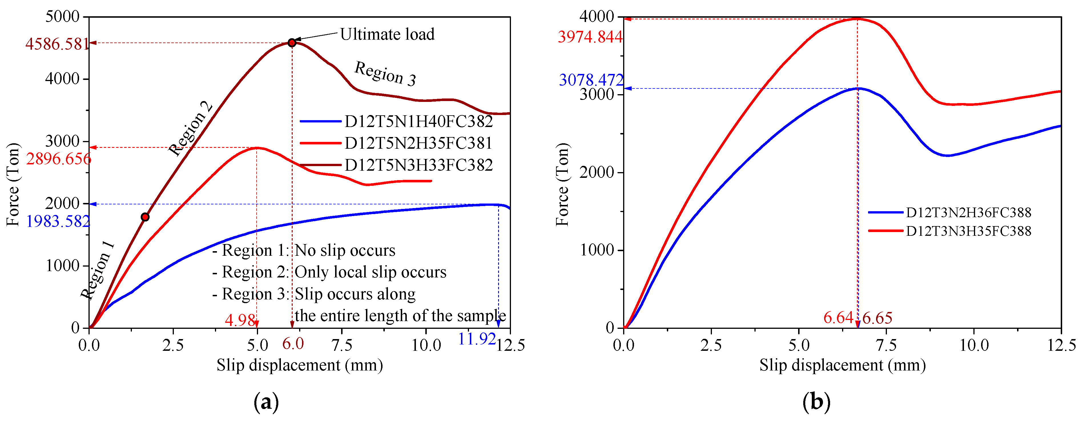
Figure 7d presents a direct load diagram on the infilled concrete, with which the bearing strength of the infilled concrete could be determined. The behavior of load-slip displacement can be separated into three regions, as indicated in Figure 8a. In region 1, the load–slip displacement relationship is linear, and the deformation of the infilled concrete primarily causes the displacement, whereas the slip between the infilled concrete and the steel tube is negligible. In region 2, the relationship between the load–slip displacement is non-linear, and localized slip begins to occur at the loaded area. The load persists until it reaches the ultimate load, which is the maximum capacity of the system. In region 3, the load begins to decline due to the destruction of the natural bond or the damage of the infilled concrete. This study mainly focused on investigating the bearing strength of the infilled concrete, and there is yet to take place any exploration of its application in construction design. Thus, allowable strength was not a concern in this research. The ultimate load, which is the force value at the intermediate point between regions 2 and 3, served as the criterion to assess the bearing strength of the model (see Figure 8a). The force at the limit point on the load–slip displacement curve was compared to evaluate the bearing strength of the infilled concrete in different models.
3.1. Influence of Number of Shear Stoppers on Bearing Strength of Infilled Concrete
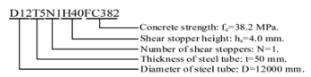
Figure 8a shows the force–slip displacement curve behavior of the first three models in Table 1. These models had the same steel tube diameter and thickness and nearly unchanged concrete compressive strengths. However, their shear stopper heights varied. The D12T5N1H40FC382 model, with one shear stopper, had the highest shear stopper height, which decreased by 17.5% in the D12T5N3H33FC382 model, which had three shear stoppers. The D12T5N2H35FC381 model, which had two shear stoppers, had a 12.5% lower shear stopper height than the D12T5N1H40FC382 model, whereas the D12T5N3H33FC382 model had a 5.7% lower height than the D12T5N2H35FC381 model. Figure 8a displays the bearing strength results among these three models, showing a 56.75% increase from the D12T5N1H40FC382 model to the D12T5N3H33FC382 model, a 31.52% increase from the D12T5N1H40FC382 model to the D12T5N2H35FC381 model, and a 36.84% increase from the D12T5N2H35FC381 model to the D12T5N3H33FC382 model. These findings indicate that the number of shear stoppers had a significant impact on the bearing strength, regardless of the decrease in shear stopper height observed in models with a high number of shear stoppers.
The investigation into the bearing strength of the infilled concrete continued, as the ratio increased from 24 to 40. In this study, two models, D12T3N2H36FC388 and D12T3N3H35FC388, were compared. These models had similar geometries and mechanical data but differed in the number of shear stoppers, with D12T3N2H36FC388 having two and D12T3N3H35FC388 having three. Figure 8b illustrates that increasing the number of shear stoppers resulted in a 22.55% increase in bearing strength from D12T3N2H36FC388 to D12T3N3H35FC388. This finding confirms that increasing the number of shear stoppers significantly improved the bearing strength of the infilled concrete. However, it is important to note that the increase in bearing strength was greater when the ratio was smaller.
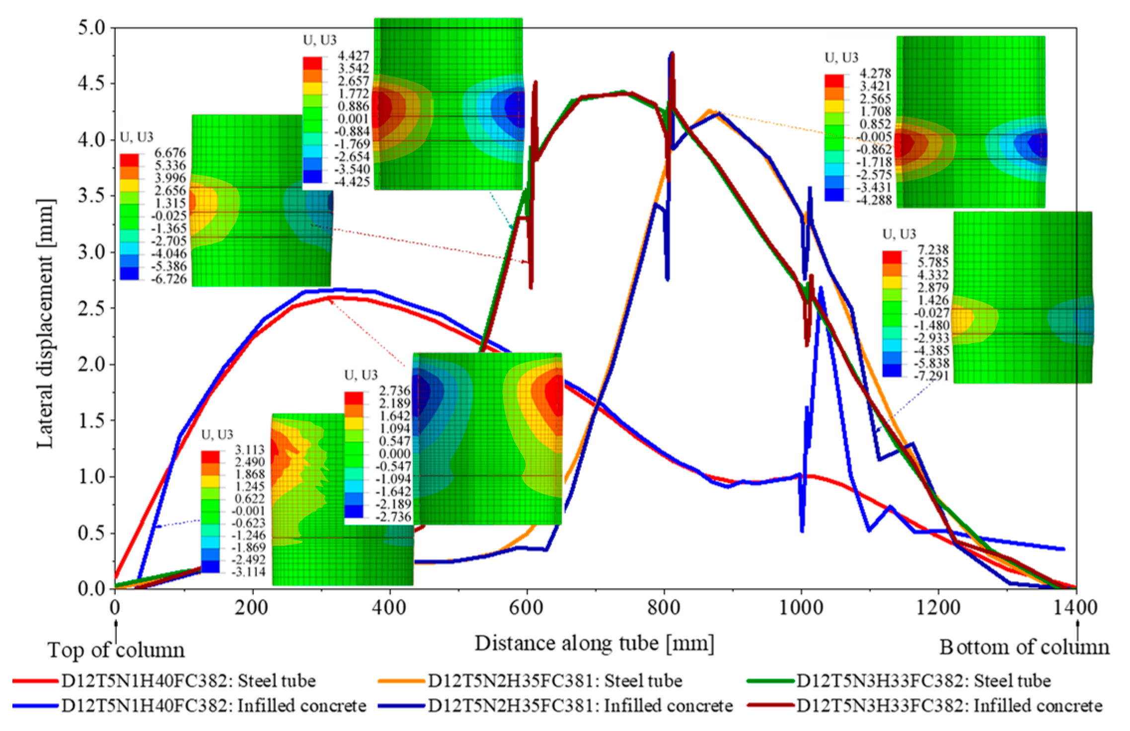
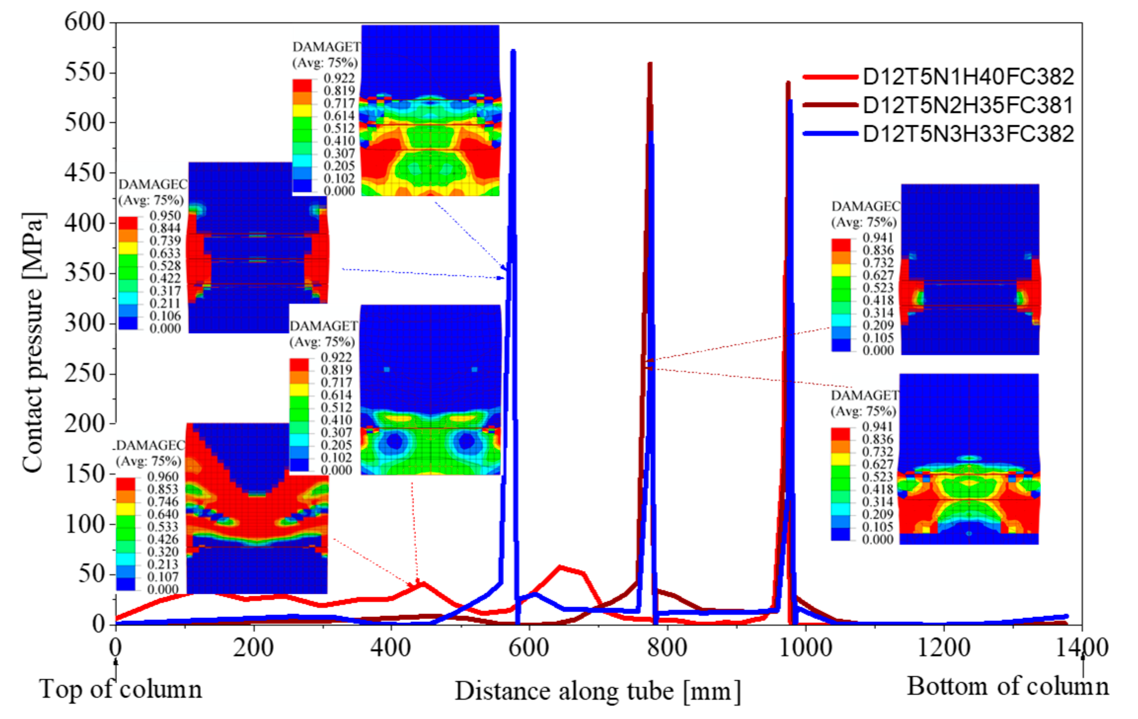
To conduct a thorough analysis of the aforementioned results, it is worth noting that the D12T5N1H40FC382 model included only one shear stopper positioned 400 mm from the bottom of the steel tube. Due to the lengthy portion of the steel tube above the shear stopper that remained unreinforced by any additional shear stoppers (1000 mm), the steel tube in this area deformed significantly under the confinement effect (see Figure 9). The contact pressure distribution in this region was greater than that of the two models D12T3N2H36FC388 and D12T3N3H35FC388, as illustrated in Figure 10. This deformation was the root cause of the premature damage to the infilled concrete in this region, as seen in the results in Figure 10. Consequently, the bearing strength of the infilled concrete in this case was notably low, and the infilled concrete exhibited relatively large slippage in comparison to the steel tube wall, as depicted in Figure 8a.
The D12T3N2H36FC388 model, which comprised two shear stoppers, and the D12T3N3H35FC388 model, which comprised three shear stoppers, caused the stress in both the infilled concrete and the steel tube wall to be redistributed towards the reinforced shear stopper areas, as demonstrated in Figure 9 and Figure 10. The shear stoppers reinforced the steel tube wall in this area, making it capable of withstanding the significant transverse pressure of the infilled concrete. Hence, the confinement effect of the infilled concrete increased, resulting in higher strength within this area. As a result, the bearing strength of the D12T3N2H36FC388 and D12T3N3H35FC388 models was significantly higher than that of the D12T5N1H40FC382 model. Additionally, the relative slippage between the infilled concrete and the steel tube wall in these two models was lower than in the D12T5N1H40FC382 model, as can be observed in Figure 8a.
3.2. Influence of Shear Stopper Height on Bearing Strength of Infilled Concrete
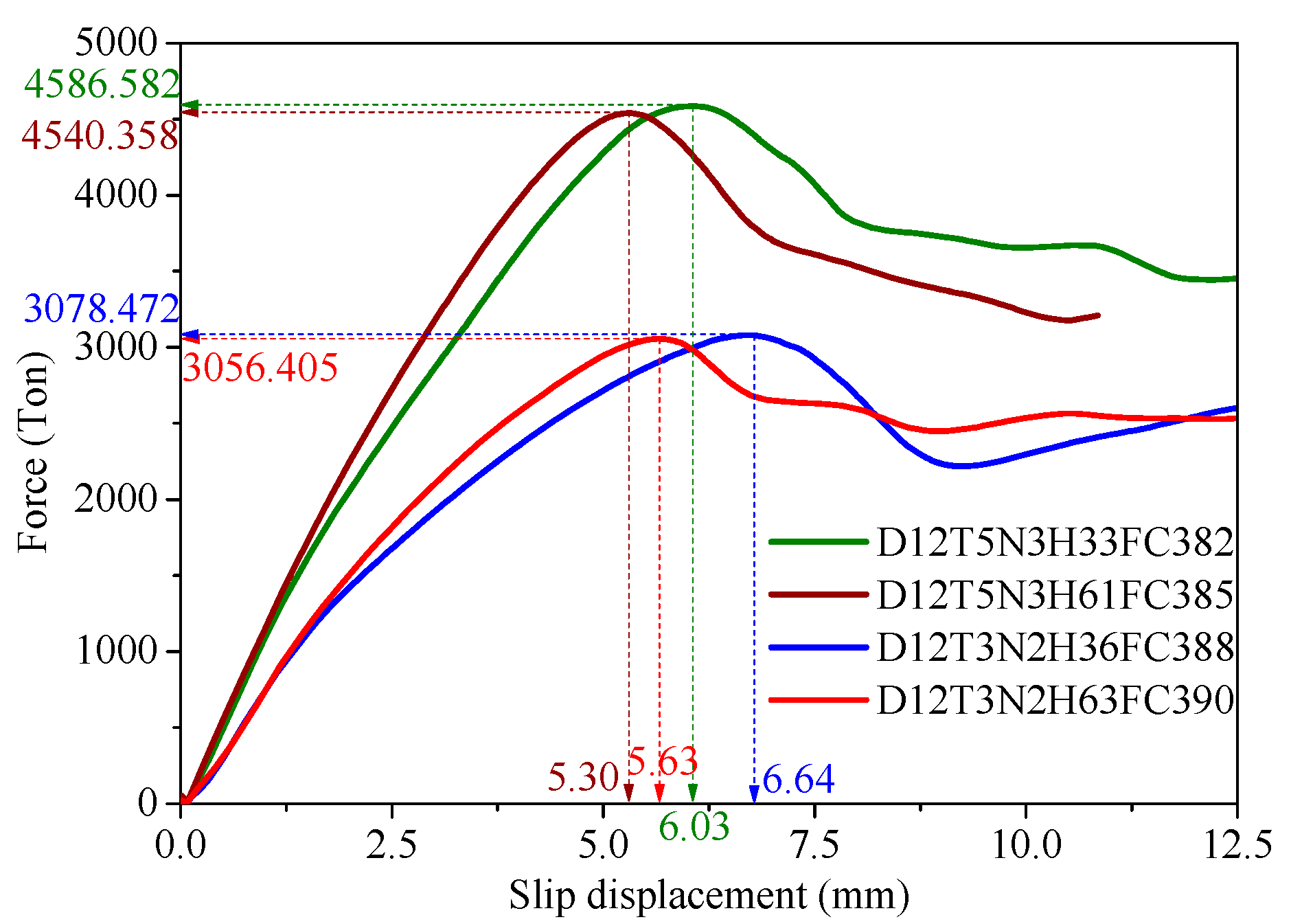
The D12T5N3H33FC382 and D12T5N3H61FC385 models had the same ratio and number of shear stoppers. Their CCSs can be considered to have been unchanged. However, the only difference between the two models was in their shear stopper height. Specifically, the D12T5N3H61FC385 model had a shear stopper height that was about 45.9% higher than that of the D12T5N3H33FC382 model. Similarly, the D12T3N2H36FC388 and D12T3N2H63FC390 models were completely similar except for their shear stopper height. The D12T3N2H63FC390 model had a shear stopper height that was about 42.86% higher than that of the D12T3N2H36FC388 model. These model pairs were used to investigate the bearing strength of the infilled concrete when the shear stopper height changed.
Figure 11 illustrates that, although the shear stopper height of the D12T5N3H61FC385 model was roughly 45.9% higher than that of the D12T5N3H33FC382 model, the bearing strength of the D12T5N3H61FC385 model was only approximately 1.0% higher than that of the D12T5N3H33FC382 model. This finding is comparable to the results obtained from the D12T3N2H36FC388 and D12T3N2H63FC390 models. The results indicate that the shear stopper height did not appear to impact the bearing strength of the infilled concrete.
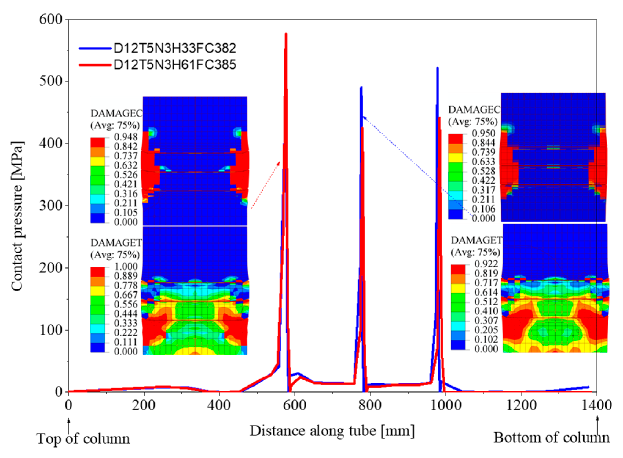
The results depicted in Figure 11 accurately represent the problem’s physical nature. The bearing strength of infilled concrete fundamentally depends on the adhesive force at the interface of the infilled concrete and steel tube wall. If this adhesive force is inadequate, the infilled concrete will slide within the steel tube, and the shear stoppers will then restrict further sliding. At this point, the bearing strength of the infilled concrete will primarily depend on CCS and shear stopper strength. In most instances, the infilled concrete tends to sustain damage before the shear stopper due to its inferior compressive and tensile strengths compared to those of the shear stopper. As a result, the height of the shear stopper exerts minimal influence on the bearing strength of the infilled concrete. Figure 12 illustrates this concept.
3.3. Influence of Concrete Compressive Strength on Bearing Strength of Infilled Concrete
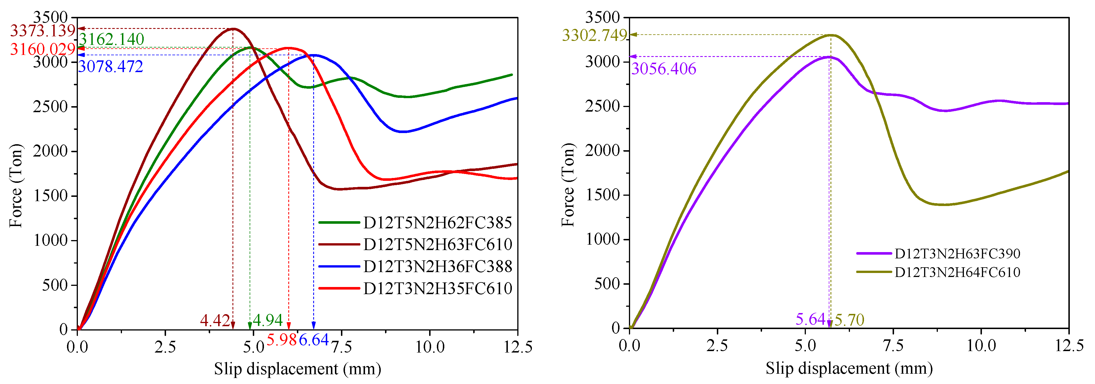
In this section, we selected three pairs of models that shared similar geometric and mechanical characteristics but differed in CCS. Our aim was to investigate the impact of CCS on the bearing strength of infilled concrete. The first pair of models comprised the D12T5N2H62FC385 model and the D12T5N2H63FC610 model. It is essential to note that the CCS of the D12T5N2H63FC610 model was 36.0% higher than that of the D12T5N2H62FC385 model. The second and third pairs of models were D12T3N2H36FC388–D12T3N2H35-FC610 and D12T3N2H63FC390–D12T3N2H64FC610, respectively. It is pertinent to mention that the CCS of the D12T3N2H35FC610 model and the D12T3N2H64FC610 model was 36.0% higher than the CCS of the D12T3N2H36FC388 model and the D12T3N2-H63FC390 model, respectively.
The simulation results presented in Figure 13 demonstrate that, for the D12T5N2H63-FC610 model, the D12T3N2H35FC610 model, and the D12T3N2H64FC610 model, the compressive strength of the infilled concrete was 6.26%, 2.58%, and 7.46% higher than that of the D12T5N2H62FC385 model, the D12T3N2H36-FC388 model, and the D12T3N2H63FC390 model, respectively. These findings indicate that, despite a 36% increase in CCS between two models with identical geometric and mechanical properties, the bearing strength of the infilled concrete between them only increased by approximately 2.58% to 7.46%. Therefore, this supports the notion that CCS does not have a significant impact on the bearing capacity of infilled concrete.
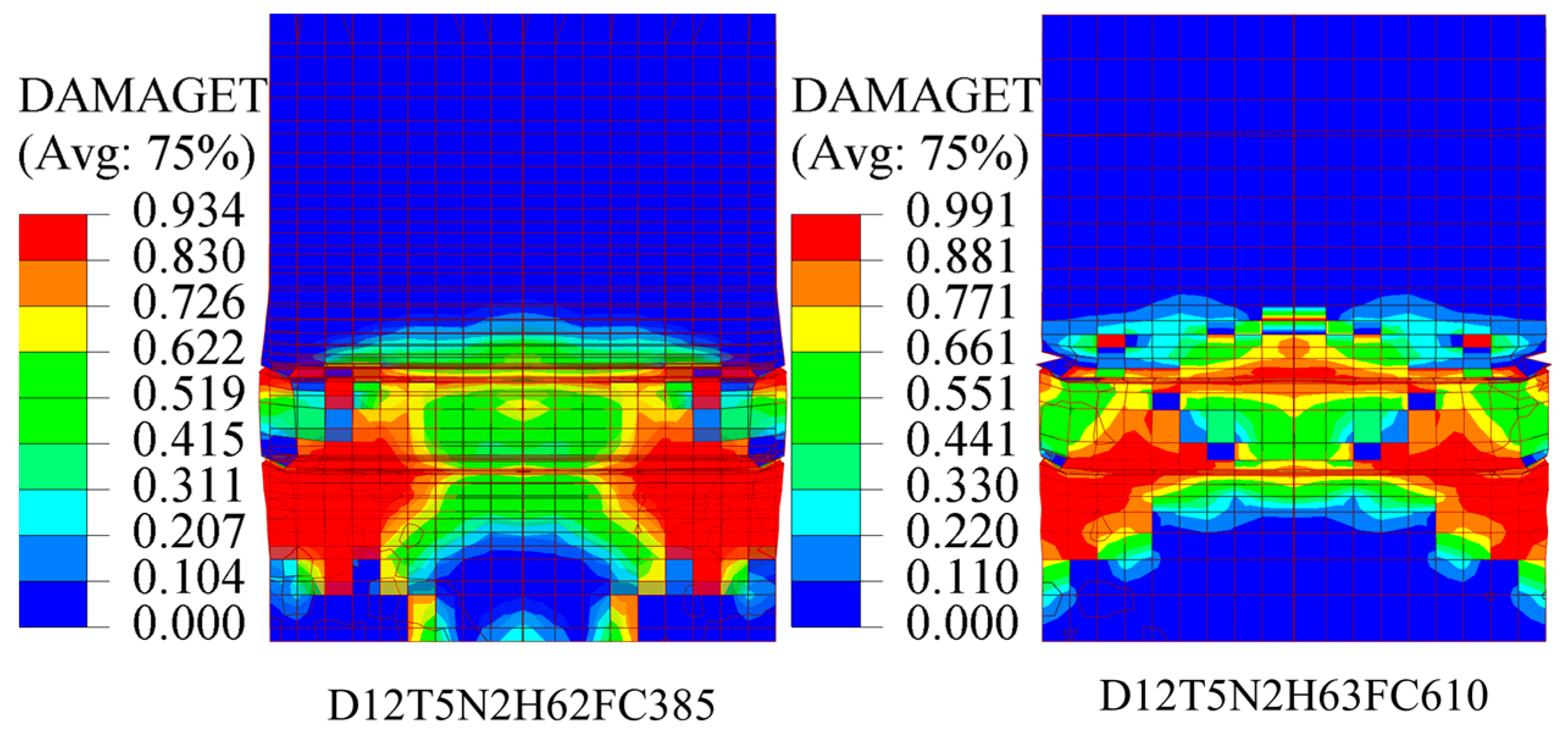
These results are reasonable because, although there was a large difference in CCS between the models, the tensile strength between them was not significantly different. Hence, the damage tensile spectrum between the models showed little variation, as demonstrated in Figure 14. It is crucial to note that when infilled concrete incurs damage, the failure occurs in tension before compression.
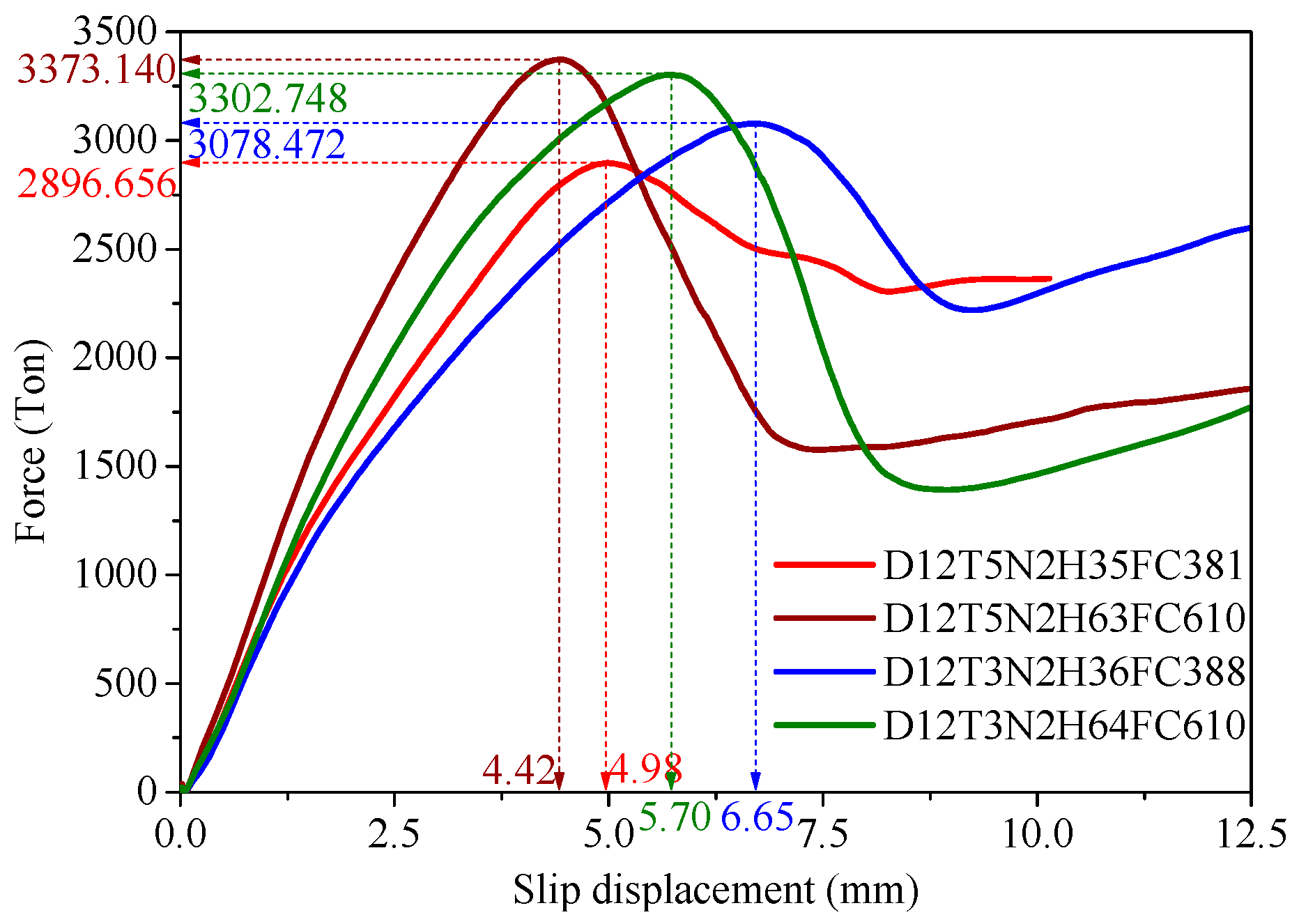
3.4. Influence of D/t Ratio on Bearing Strength of Infilled Concrete
To investigate how the ratio affected the bearing strength of the infilled concrete, two pairs of models were selected. These models had the same geometric and mechanical properties, except for the ratio, which varied. The first pair consisted of the D12T5N2H35FC381 and D12T3N2H36FC388 models, whereas the second pair comprised the D12T5N2H63FC610 and D12T3N2H64FC610 models. The ratio increased by approximately 40% (from 24 to 40) when comparing the D12T5N2H35FC381 and D12T3N2H36FC388 models. Similarly, the ratio of the D12T5N2H63FC610 and D12T3N2H64FC610 models increased as well.
The ratio, which changed by approximately 40%, was considerable; however, Figure 15 illustrates that the bearing strength between the two pairs of models only varied by approximately 2% to 6%. This indicates that the ratio had a minimal impact on the bearing strength of the column’s infilled concrete. This finding is entirely logical since all damage to the models was due to the tensile damage of the infilled concrete. Nevertheless, the tensile strength of all models was relatively low and did not significantly differ from one another.
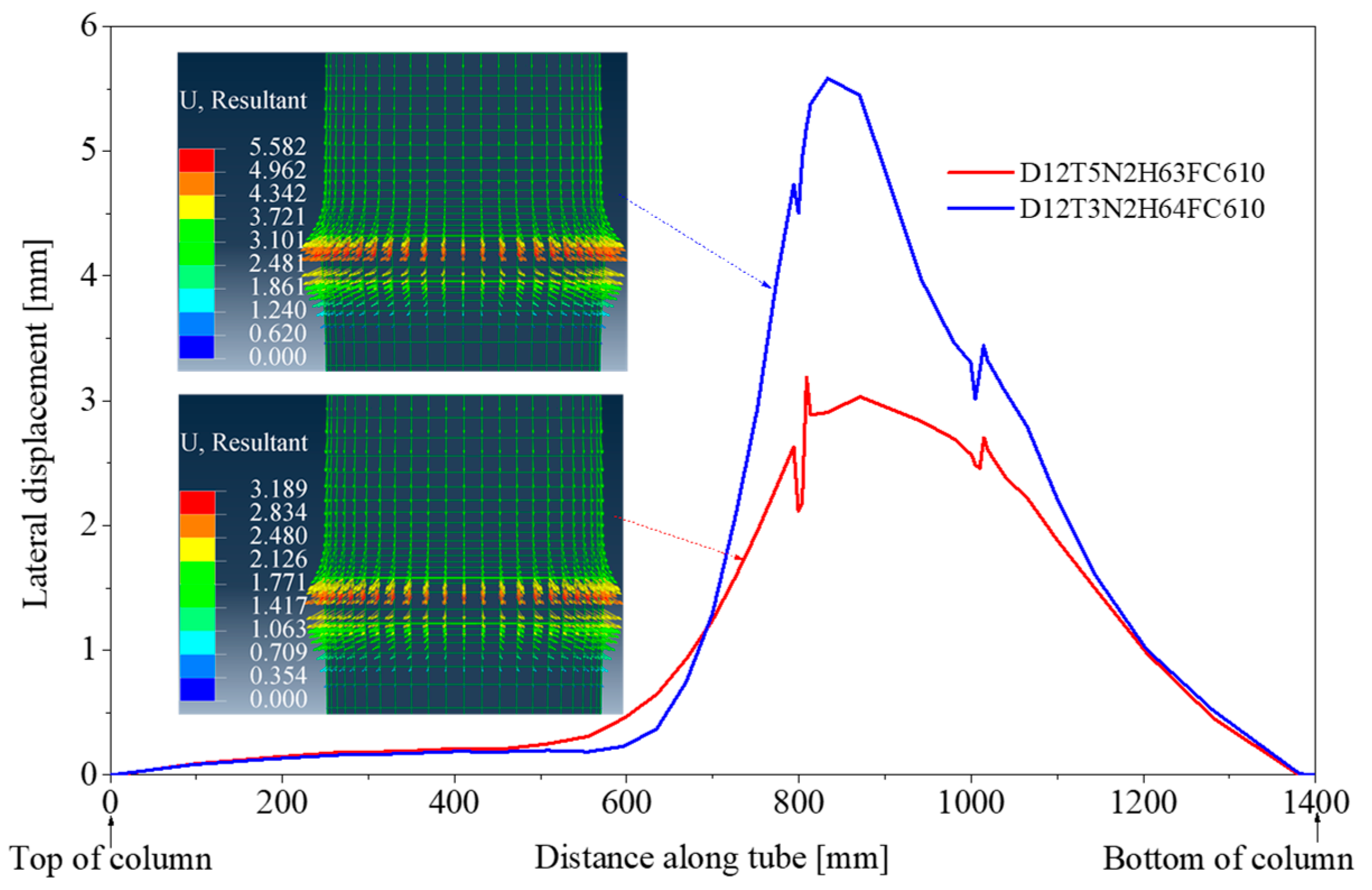
Please note that, in this study, as increased, the steel tube wall thickness decreased, whereas the column diameter remained constant. Therefore, to assess the validity of the transverse displacement of the steel tube wall, it was necessary to check the results. The data presented in Figure 16 indicate that the transverse displacement of model D12T3N2H64-FC610 (where the steel tube thickness was reduced by 40%) increased by 42.87% compared to model D12T5N2H63FC610 (the original model with a steel tube wall thickness of 50 mm). This suggests that the confinement effect of the infilled concrete in model D12T3N2H64FC610 decreased but that the bearing strength remained relatively unaffected. This further supports the conclusion that concrete tensile damage significantly affects the bearing strength, as demonstrated in Figure 15.
Based on the analyzed results, we cannot accurately determine the degree of influence that each investigation parameter had on the bearing strength of the infilled concrete, nor can we evaluate how these parameters interacted with each other. To address this issue, this study employed analysis of variance (ANOVA), which is described in the following section.
3.5. Investigation of the Impact of Geometric and Mechanical Parameters on Bearing Strength
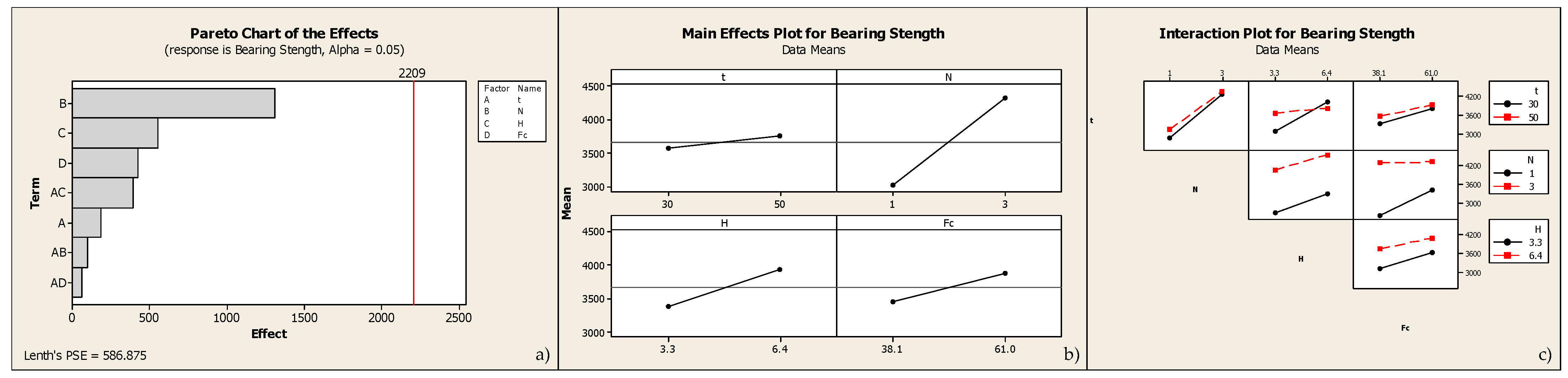
In this section, ANOVA was utilized to investigate the degree of influence of the factors and their interactions on bearing strength. The four factors examined were the ratio (A), the number of shear stoppers (B), the height of the shear stoppers (C), and the CCS (D). Each factor was examined at only two levels, low and high. The results of the multilevel factorial design are presented in Table 2, with “bearing strength” taken from the simulation results and provided in the last column.
The results of the analysis in Figure 17a indicate the influence of the four investigation parameters on bearing strength, arranged in descending order as follows: number of shear stoppers, shear stopper height, CCS, and ratio. The figure also illustrates that the interaction between the number of shear stoppers and the height of the shear stoppers had a considerable effect on the bearing strength. This implies that if only one shear stopper is used, a significant increase in its height may not greatly affect bearing strength. However, if both the number of shear stoppers and their height are increased simultaneously, it may significantly impact the bearing strength. Figure 17b outlines the impact of each parameter on bearing strength.
Considering the interaction between parameters is essential in the design process to achieve the desired results. Interaction analysis allows us to understand how the parameters coordinate to influence the outcome. For instance, observing the interaction between CCS and the number of shear stoppers in Figure 17c revealed that, even when the number of shear stoppers was high, increasing the CCS did not impact the bearing strength when the shear stopper height was low. However, when only the shear stopper height interacted with the number of shear stoppers, it significantly affected the bearing strength. In other cases, when shear stopper height interacts with other parameters, it may not substantially impact bearing strength.
4. Conclusions
The parametric method utilizes numerical results to demonstrate the impact of geometric and mechanical parameters on the bearing strength of infilled concrete in circular CFST columns with a large diameter. Several conclusions were drawn from this study:
- The number of shear stoppers was among the most critical parameters that significantly impacted the bearing strength of the infilled concrete in circular CFST columns with a large diameter. When the number of shear stoppers was high, the bearing strength of the infilled concrete increased considerably. Firstly, the high number of shear stoppers increased the contact capacity between the infilled concrete and the steel tube, allowing them to work together efficiently. This mutual transmission mechanism enhanced the bearing capacity of the CFST column. Secondly, the shear stoppers served as reinforcing ribs for the steel tube wall, enhancing its ability to resist lateral deformation, preventing local buckling, increasing the confinement effect, and enhancing the concrete strength. Thus, they considerably increased the bearing capacity of the CFST column.
- Although the analysis results indicate that the height of the shear stopper was one of the parameters that affected the bearing strength of the infilled concrete, ranked second only to the number of shear stoppers, increasing the height of the shear stopper did not significantly enhance the bearing strength of the infilled concrete. However, this parameter considerably improved the bearing strength when complemented with an increase in the compressive strength of the concrete. Thus, when seeking to improve the bearing strength of infilled concrete, we must consider adjusting the parameters to collaborate synergistically to achieve maximum efficacy.
- The study confirmed that an increase in concrete strength had only a slight effect on the bearing strength. Additionally, the use of high-strength concrete reduced the lateral expansion of the infilled concrete, decreasing its confinement effect. Furthermore, when the infilled concrete slipped through the shear stoppers, the concrete part interacting with the shear stoppers could have been damaged, leading to the incapacity of the infilled concrete to bear the load. Therefore, it is necessary to carefully consider reinforcing the compressive strength of concrete to achieve maximum efficiency while avoiding unnecessary waste.
Author Contributions
Conceptualization, M.P.; Software, M.P.; Formal analysis, M.P.and C.-T.D.; Investigation, N.-H.D. and C.-T.D.; Data curation, N.-H.D. and C.-T.D.; Writing—original draft, M.P.; Writing—review & editing, N.-H.D. and H.-C.T. All authors have read and agreed to the published version of the manuscript.
Funding
This work is supported by the University of Science and Technology–The University of Da Nang under research project No. T2022-02-54. The authors gratefully acknowledge this financial support.
Data Availability Statement
The data presented in this study are available in the article.
Conflicts of Interest
The authors declare no conflicts of interest.
References
- Tao, Z.; Han, L.-H.; Wang, D.-Y. Strength and ductility of stiffened thin-walled hollow steel structural stub columns filled with concrete. Thin-Walled Struct. 2008, 46, 1113–1128. [Google Scholar] [CrossRef]
- Moon, J.; Kim, J.J.; Lee, T.-H.; Lee, H.-E. Prediction of axial load capacity of stub circular concrete-filled steel tube using fuzzy logic. J. Constr. Steel Res. 2014, 101, 184–191. [Google Scholar] [CrossRef]
- Han, L.-H.; Li, W.; Bjorhovde, R. Developments and advanced applications of concrete-filled steel tubular (CFST) structures: Members. J. Constr. Steel Res. 2014, 100, 211–228. [Google Scholar] [CrossRef]
- Li, G.-C.; Chen, B.-W.; Yang, Z.-J.; Liu, Y.-P.; Feng, Y.-H. Experimental and numerical behavior of eccentrically loaded square concrete-filled steel tubular long columns made of high-strength steel and concrete. Thin-Walled Struct. 2021, 159, 107289. [Google Scholar] [CrossRef]
- Roeder, C.W. Overview of hybrid and composite systems for seismic design in the United States. Eng. Struct. 1998, 20, 355–363. [Google Scholar] [CrossRef]
- Al-Khaleefi, A.M.; Terro, M.J.; Alex, A.P.; Wang, Y. Prediction of fire resistance of concrete filled tubular steel columns using neural networks. Fire Saf. J. 2002, 37, 339–352. [Google Scholar] [CrossRef]
- Chung, K.; Park, S.; Choi, S. Fire resistance of concrete filled square steel tube columns subjected to eccentric axial load. Int. J. Steel Struct. 2009, 9, 69–76. [Google Scholar] [CrossRef]
- Kodur, V.; Franssen, J.-M. Structures in Fire. In Proceedings of the Sixth International Conference, SiF’10: Preface, East Lansing, MI, USA, 2–4 June 2010; Kellogg Hotel & Conference Center Michigan State University. DEStech Publications, Inc.: Lancaster, PA, USA, 2010; p. 1026. [Google Scholar]
- Varma Amit, H.; Ricles James, M.; Sause, R.; Lu, L.-W. Experimental Behavior of High Strength Square Concrete-Filled Steel Tube Beam-Columns. J. Struct. Eng. 2002, 128, 309–318. [Google Scholar] [CrossRef]
- Roeder, C.W.; Cameron, B.; Brown, C.B. Composite Action in Concrete Filled Tubes. J. Struct. Eng. 1999, 125, 477–484. [Google Scholar] [CrossRef]
- Marshall, I.H. Composite Structures. In Proceedings of the 1st. International Conference on Composite Structures, Paisley College of Technology, Paisley, Scotland, 16–18 September 1981; Applied Science Publishers: London, UK; Englewood, NJ, USA, 1981. [Google Scholar]
- British-Standards-Institution. Steel, Concrete and Composite Bridges—Part 5: Code of practice for design of composite bridges. In B.S. (Series); British Standards Institution: London, UK, 1979; p. 57. [Google Scholar]
- Furlong Richard, W. Strength of Steel-Encased Concrete Beam Columns. J. Struct. Div. 1967, 93, 113–124. [Google Scholar] [CrossRef]
- Virdi, K.S.; Dowling, P.J. The Ultimate Strength of Composite Columns in Biaxial Bending. Proc. Inst. Civ. Eng. 1973, 55, 251–272. [Google Scholar] [CrossRef]
- Hunaiti, Y.M.; Shakir-Khalil, H. Behaviour of Battened Composite Columns; University of Manchester: Manchester, UK, 1985; p. 204. [Google Scholar]
- Hunaiti Yasser, M. Bond Strength in Battened Composite Columns. J. Struct. Eng. 1991, 117, 699–714. [Google Scholar] [CrossRef]
- Xu, C.; Chengkui, H.; Decheng, J.; Yuancheng, S. Push-out test of pre-stressing concrete filled circular steel tube columns by means of expansive cement. Constr. Build. Mater. 2009, 23, 491–497. [Google Scholar] [CrossRef]
- Qu, X.; Chen, Z.; Nethercot, D.A.; Gardner, L.; Theofanous, M. Push-out tests and bond strength of rectangular CFST columns. Steel Compos. Struct. 2015, 19, 21–41. [Google Scholar] [CrossRef]
- Virdi, K.S.; Dowling, P.J. Bond strength in concrete filled circular steel tubes. In CESLIC Report CC11; Department of Civil Engineering, Imperial College: London, UK, 1975. [Google Scholar]
- Virdi, K.S.; Dowling, P.J. Bond Strength in Concrete Filled Steel Tubes; IVBH: San Antonio, TX, USA, 1980. [Google Scholar]
- Johansson, M.; Gylltoft, K. Mechanical Behavior of Circular Steel–Concrete Composite Stub Columns. J. Struct. Eng. 2002, 128, 1073–1081. [Google Scholar] [CrossRef]
- Guan, M.; Lai, Z.; Xiao, Q.; Du, H.; Zhang, K. Bond behavior of concrete-filled steel tube columns using manufactured sand (MS-CFT). Eng. Struct. 2019, 187, 199–208. [Google Scholar] [CrossRef]
- Starossek, U.; Falah, N. The interaction of steel tube and concrete core in concrete-filled steel tube columns. In Proceedings of the Tubular Structures XII: Proceedings of Tubular Structures XII, Shanghai, China, 8–10 October 2008; pp. 75–84. [Google Scholar]
- Starossek, U.; Falah, N.; Löhning, T. Numerical Analyses of the Force Transfer in Concrete-Filled Steel Tube. In Proceedings of the 4th International Conference on Advances in Structural Engineering and Mechanics(ASEM’08), Jeju, Republic of Korea, 30 May 2010; Techno-Press: Daejeon, Republic of Korea, 2010; pp. 241–256. [Google Scholar]
- Petrus, C.; Abdul Hamid, H.; Ibrahim, A.; Nyuin, J.D. Bond strength in concrete filled built-up steel tube columns with tab stiffeners. Can. J. Civ. Eng. 2011, 38, 627–637. [Google Scholar] [CrossRef]
- Song, T.; Tao, P.Z.; Uy, B.; Han, L.-H. Bond strength in full-scale concrete-filled steel tubular columns. In Proceedings of the Advances in Structural Engineering and Mechanics (ASEM15), Incheon, Republic of Korea, 25–29 August 2015. [Google Scholar]
- Ferrotto, M.F.; Fenu, L.; Xue, J.-Q.; Briseghella, B.; Chen, B.-C.; Cavaleri, L. Simplified equivalent finite element modelling of concrete-filled steel tubular K-joints with and without studs. Eng. Struct. 2022, 266, 114634. [Google Scholar] [CrossRef]
- Li, N.; Xi, Y.; Li, H.; Zhang, G.; Ren, T.; Mu, X. Bearing Strength of Concrete-Filled Steel Tube Reinforced with Internal Transverse Stiffened Bars under Axial Compression. Scanning 2022, 2022, 1704544. [Google Scholar] [CrossRef]
- Wu, R.-M.; Wang, L.-Q.; Tong, J.-Z.; Tong, G.-S.; Gao, W. Elastic buckling formulas of multi-stiffened corrugated steel plate shear walls. Eng. Struct. 2024, 300, 117218. [Google Scholar] [CrossRef]
- Tong, J.; Wu, R.; Wang, L. Experimental and numerical investigations on seismic behavior of stiffened corrugated steel plate shear walls. Earthq. Eng. Struct. Dyn. 2023, 52, 3551–3574. [Google Scholar] [CrossRef]
- Yu, C.-Q.; Tong, G.-S.; Tong, J.-Z.; Zhang, J.-W.; Li, X.-G.; Xu, S.-L. Experimental and numerical study on seismic performance of L-shaped multi-cellular CFST frames. J. Constr. Steel Res. 2024, 213, 108360. [Google Scholar] [CrossRef]
- Ypma, T.J. Historical Development of the Newton–Raphson Method. SIAM Rev. 1995, 37, 531–551. [Google Scholar] [CrossRef]
- International-Federation-for-Structural-Concrete-(FIB). Fib Model Code 2010. In Structural Concrete; Wiley Subscription Services, Inc.: London, UK, 2010; pp. 74–150. [Google Scholar] [CrossRef]
- Krätzig, W.B.; Pölling, R. An elasto-plastic damage model for reinforced concrete with minimum number of material parameters. Comput. Struct. 2004, 82, 1201–1215. [Google Scholar] [CrossRef]
- Mander, J.B.; Priestley, M.J.N.; Park, R. Theoretical Stress-Strain Model for Confined Concrete. J. Struct. Eng. 1988, 114, 1804–1826. [Google Scholar] [CrossRef]
- Liang, Q.Q. High strength circular concrete-filled steel tubular slender beam–columns, Part I: Numerical analysis. J. Constr. Steel Res. 2011, 67, 164–171. [Google Scholar] [CrossRef]
- Liang, Q.Q. Performance-based analysis of concrete-filled steel tubular beam–columns, Part I: Theory and algorithms. J. Constr. Steel Res. 2009, 65, 363–372. [Google Scholar] [CrossRef]
- Gadamchetty, G.; Pandey, A.; Gawture, M. On Practical Implementation of the Ramberg-Osgood Model for FE Simulation. SAE Int. J. Mater. Manuf. 2016, 9, 200–205. [Google Scholar] [CrossRef]
- Rezaeian, A.; Jahanbakhti, E.; Fanaie, N. Numerical Study of Panel Zone in a Moment Connection without Continuity Plates. J. Earthq. Eng. 2022, 26, 930–948. [Google Scholar] [CrossRef]
- Francavilla, A.; Zienkiewicz, O. A note on numerical computation of elastic contact problems. Int. J. Numer. Methods Eng. 1975, 9, 913–924. [Google Scholar] [CrossRef]
- Chan, S.K.; Tuba, I.S. A finite element method for contact problems of solid bodies—Part I. Theory and validation. Int. J. Mech. Sci. 1971, 13, 615–625. [Google Scholar] [CrossRef]
- Hughes, T.J.R.; Taylor, R.L.; Sackman, J.L.; Curnier, A.; Kanoknukulchai, W. A finite element method for a class of contact-impact problems. Comput. Methods Appl. Mech. Eng. 1976, 8, 249–276. [Google Scholar] [CrossRef]
- Kikuchi, N.; Oden, J.T. Contact Problems in Elasticity: A Study of Variational Inequalities and Finite Element Methods; Society for Industrial and Applied Mathematics: Philadelphia, PA, USA, 1988. [Google Scholar]
- Han, L.-H.; Yao, G.-H.; Tao, Z. Performance of concrete-filled thin-walled steel tubes under pure torsion. Thin-Walled Struct. 2007, 45, 24–36. [Google Scholar] [CrossRef]
Figure 1.
Forms of reinforcement for the inner surface of the steel tube: (a) force transfer mechanism for shear connector bond [24]; (b) shear studs in circular steel tube specimen and internal ring in square steel tube specimen [26].

Figure 2.
New stiffening model proposed by Petrus: (a) four longitudinal stiffeners; (b) two tab stiffeners and two longitudinal stiffeners [25].
Figure 2.
New stiffening model proposed by Petrus: (a) four longitudinal stiffeners; (b) two tab stiffeners and two longitudinal stiffeners [25].

Figure 3.
Newton–Raphson algorithm: (a) load level process for NFEA; (b) steps, increments, and iterations procedure.
Figure 3.
Newton–Raphson algorithm: (a) load level process for NFEA; (b) steps, increments, and iterations procedure.

Figure 4.
The behavior curve of the infilled concrete in the CFST, taking into account the confinement effect: (a) compressive stress–strain curve; (b) tensile stress–strain curve.
Figure 4.
The behavior curve of the infilled concrete in the CFST, taking into account the confinement effect: (a) compressive stress–strain curve; (b) tensile stress–strain curve.

Figure 5.
Constitutive model of steel: (a) steel tube; (b) shear stopper.

Figure 6.
The geometrical and mechanical properties of the simulation models.

Figure 7.
A typical mesh of CFSTs and its working principle: (a) steel tube reinforced by one shear stopper; (b) steel tube reinforced by two shear stoppers; (c) steel tube reinforced by three shear stoppers; (d) working principal diagram.
Figure 7.
A typical mesh of CFSTs and its working principle: (a) steel tube reinforced by one shear stopper; (b) steel tube reinforced by two shear stoppers; (c) steel tube reinforced by three shear stoppers; (d) working principal diagram.

Figure 8.
The force-slip displacement curves of infilled concrete in the case of steel tube reinforced with different numbers of shear stoppers: (a) steel tubes with ; (b) steel tubes with .
Figure 8.
The force-slip displacement curves of infilled concrete in the case of steel tube reinforced with different numbers of shear stoppers: (a) steel tubes with ; (b) steel tubes with .

Figure 9.
Lateral displacement distributed along the column and its lateral displacement spectrum.

Figure 10.
Distributed contact pressure along the column and the compression damage spectrum in case the number of shear stoppers changes.
Figure 10.
Distributed contact pressure along the column and the compression damage spectrum in case the number of shear stoppers changes.

Figure 11.
The force-slip displacement curves of infilled concrete in the case of steel tube reinforced with different the shear stopper height.
Figure 11.
The force-slip displacement curves of infilled concrete in the case of steel tube reinforced with different the shear stopper height.

Figure 12.
Distributed contact pressure along the column in models, and compression/tensile damage spectrum of the two specimens D12T5N3H33FC382 and D12T5N3H61FC385.
Figure 12.
Distributed contact pressure along the column in models, and compression/tensile damage spectrum of the two specimens D12T5N3H33FC382 and D12T5N3H61FC385.

Figure 13.
The force-slip displacement curves of infilled concrete in the case of using various types of CCS.
Figure 13.
The force-slip displacement curves of infilled concrete in the case of using various types of CCS.

Figure 14.
Tension damage spectrum of the D12T5N2H62FC385 model and the D12T5N2H63FC610 model.

Figure 15.
The force-slip displacement curves of infilled concrete in the case of using steel tubes with different ratios.
Figure 15.
The force-slip displacement curves of infilled concrete in the case of using steel tubes with different ratios.

Figure 16.
Lateral displacement distributed along the column and the lateral displacement spectrum of the D12T5N2H63FC610 and D12T3N2H64FC610 models.
Figure 16.
Lateral displacement distributed along the column and the lateral displacement spectrum of the D12T5N2H63FC610 and D12T3N2H64FC610 models.

Figure 17.
Analysis of variance vs. bearing strength: (a) Pareto chart; (b) main effect plots (data means); (c) interaction plot (data means).
Figure 17.
Analysis of variance vs. bearing strength: (a) Pareto chart; (b) main effect plots (data means); (c) interaction plot (data means).


Table 1.
The geometrical and mechanical properties of the simulation models.
| No. | Mark 1 | D (mm) | t (mm) | D/t | (mm) | Concrete Compressive Strength (MPa) | Pipe Height H (mm) | |
|---|---|---|---|---|---|---|---|---|
| 1 | D12T5N1H40FC382 | 1200 | 50 | 24 | 1 | 4.0 | 38.2 | 1400 |
| 2 | D12T5N2H35FC381 | 1200 | 50 | 24 | 2 | 3.5 | 38.1 | 1400 |
| 3 | D12T5N3H33FC382 | 1200 | 50 | 24 | 3 | 3.3 | 38.2 | 1400 |
| 4 | D12T5N2H62FC385 | 1200 | 50 | 24 | 2 | 6.2 | 38.5 | 1400 |
| 5 | D12T5N3H61FC385 | 1200 | 50 | 24 | 3 | 6.1 | 38.5 | 1400 |
| 6 | D12T5N2H63FC610 | 1200 | 50 | 24 | 2 | 6.3 | 61.0 | 1400 |
| 7 | D12T3N2H36FC388 | 1200 | 30 | 40 | 2 | 3.6 | 38.8 | 1400 |
| 8 | D12T3N3H35FC388 | 1200 | 30 | 40 | 3 | 3.5 | 38.8 | 1400 |
| 9 | D12T3N2H63FC390 | 1200 | 30 | 40 | 2 | 6.3 | 39.0 | 1400 |
| 10 | D12T3N2H35FC610 | 1200 | 30 | 40 | 2 | 3.5 | 61.0 | 1400 |
| 11 | D12T3N2H64FC610 | 1200 | 30 | 40 | 2 | 6.4 | 61.0 | 1400 |
1 The meanings of the symbols provided in the "Mark" column of Table 1 are as follows:![Designs 08 00009 i001]() .
.
 .
.Table 2.
Multilevel factorial design.
| StdOrder | RunOrder | CenterPt | Blocks | t | N | hw | Bearing Strength | |
|---|---|---|---|---|---|---|---|---|
| 7 | 1 | 1 | 1 | 30 | 3 | 6.4 | 38.1 | 4505 |
| 4 | 2 | 1 | 1 | 50 | 3 | 3.3 | 38.1 | 4100 |
| 2 | 3 | 1 | 1 | 50 | 1 | 3.3 | 61 | 3250 |
| 6 | 4 | 1 | 1 | 50 | 1 | 6.4 | 38.1 | 3050 |
| 1 | 5 | 1 | 1 | 30 | 1 | 3.3 | 38.1 | 2150 |
| 5 | 6 | 1 | 1 | 30 | 1 | 6.4 | 61 | 3580 |
| 8 | 7 | 1 | 1 | 50 | 3 | 6.4 | 61 | 4620 |
| 3 | 8 | 1 | 1 | 30 | 3 | 3.3 | 61 | 4050 |
Disclaimer/Publisher’s Note: The statements, opinions and data contained in all publications are solely those of the individual author(s) and contributor(s) and not of MDPI and/or the editor(s). MDPI and/or the editor(s) disclaim responsibility for any injury to people or property resulting from any ideas, methods, instructions or products referred to in the content. |
© 2024 by the authors. Licensee MDPI, Basel, Switzerland. This article is an open access article distributed under the terms and conditions of the Creative Commons Attribution (CC BY) license (https://creativecommons.org/licenses/by/4.0/).
Share and Cite
MDPI and ACS Style
Pham, M.; Dinh, N.-H.; Dang, C.-T.; Truong, H.-C. Numerical Study of Bearing Strength of Infilled Concrete in Large Diameter CFST Column Reinforced by Shear Stoppers. Designs 2024, 8, 9. https://doi.org/10.3390/designs8010009
AMA Style
Pham M, Dinh N-H, Dang C-T, Truong H-C. Numerical Study of Bearing Strength of Infilled Concrete in Large Diameter CFST Column Reinforced by Shear Stoppers. Designs. 2024; 8(1):9. https://doi.org/10.3390/designs8010009
Chicago/Turabian StylePham, My, Ngoc-Hieu Dinh, Cong-Thuat Dang, and Hoai-Chinh Truong. 2024. "Numerical Study of Bearing Strength of Infilled Concrete in Large Diameter CFST Column Reinforced by Shear Stoppers" Designs 8, no. 1: 9. https://doi.org/10.3390/designs8010009
Article Metrics
Article metric data becomes available approximately 24 hours after publication online.